
The role of PFC in a circuit is a key parameter for measuring the effective application of power. So how is power factor generated?
To explain the process of power factor, the rectified DC voltage is input to the PFC circuit after being corrected by the rectifier bridge. Before discussing the PFC (Power Factor Correction) circuit, let’s briefly understand what “power factor (PF)” means.
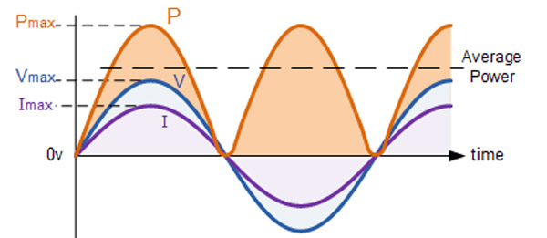
Power factor (PF) refers to the ratio of actual power (effective power) to apparent power (rated power) (kW/kVA). As we all know, power P equals voltage multiplied by current (P=VxI). Additionally, there are two basic circuit loads in a circuit: resistance (made up of various resistances in the power supply circuit) and reactance (made up of inductors and capacitors in the power supply circuit).
If the entire circuit is a linear load (a load with a constant circuit impedance), then the power supply voltage and current will show a sine wave with the same phase. In a pure resistive load circuit, at each moment the product of the voltage and current is “positive” as the voltage and current reverse polarity at the same time. This means that there is no “reverse direction (negative pole direction)” energy movement in the circuit, and the load power generated at this time is known as “actual power”.
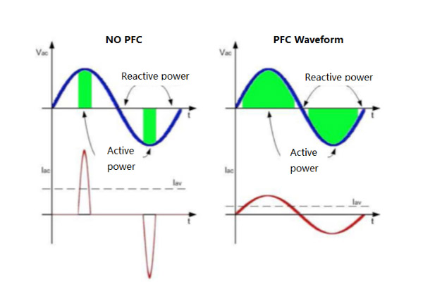
In a pure reactive load circuit, there will be a time lag and phase difference between the voltage and current (with a maximum theoretical value of 90 degrees and a general value of 45 degrees). Therefore, the product of voltage and current may not always be “positive” at every moment. In the first half cycle, energy is “positive”, while in the second half cycle, this energy flows back to the grid. Therefore, if calculated over one cycle, the energy obtained by the power source is “zero”.
In practical applications, there are usually a large number of resistors, inductors, and capacitors in a circuit, all of which will have loads at the same time. Thus, energy will be generated in different directions. All positively generated energy is known as “actual power”, while energy flowing back to the grid is known as “reactive power”. The combination of “actual power” and “reactive power” is what we call “apparent power”.
JPTPOWER has many years of experience in the development of power adapters, can provide high PF power adapters, you can consult our technicians, they can provide professional service.
To sum up, power factor is a crucial parameter for measuring the effective application of power in a circuit. It can be generated through rectifying DC voltage and correcting it through the PFC circuit. In practical applications, circuit loads usually consist of resistors, inductors, and capacitors, leading to both actual power and reactive power. Understanding power factor and its generation process is important for efficient energy use and effective power management.