
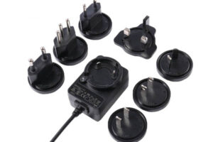
As a power conversion device, power adapters are ubiquitous in daily life, but most people rarely know their basic knowledge and functions. There are generally two types of power adapters: plug-in and desktop, which are often used in electronic devices such as mobile phones, cameras, computers, game consoles, set-top boxes, and massagers. JPTPOWER has obtained product safety certifications such as IEC62368, IEC61558, IEC60335, and UL 1310.
The working principle of the power adapter is to use electronic switching devices (such as transistors, field-effect transistors, thyristors, etc.) to control the circuit, so that the electronic switching devices can continuously “turn on” and “turn off”, thereby achieving AC-DC, DC/DC voltage conversion, and adjustable output voltage and automatic voltage stabilization. Due to the complexity of the switching power supply circuit, multiple protection circuits, and difficult maintenance, it is very important for maintenance personnel to be proficient in the basic components and working principles of the switching power supply in order to quickly troubleshoot switching power supply failures.
In the use of power adapters, it is inevitable that some faults will occur after a long period of time. So, what are the common faults of power adapters and how to solve them?
I. “See, smell, ask, measure” when power is off
First of all, before the switch power supply is powered on, it is necessary to measure the voltage at both ends of the high-voltage capacitor. If the power adapter does not start oscillation or fails due to an open circuit of the switch tube, the voltage at both ends of the high-voltage filter capacitor is generally not discharged, and this voltage is about 300V, which needs to be handled with extra care.
Since the repair of the power supply requires contact with 220V high voltage, once the human body contacts with a voltage above 36V, there is a risk of life. Therefore, in the power-off state, it is necessary to observe whether there is obvious fuse blowing, short circuit, component damage, etc. in the power supply. If a component on the power supply PCB board is found to be broken, this component should be checked in a targeted manner, which is generally the main cause of the fault.
In addition, you need to smell inside the power supply to see if there is any burnt smell, check whether there are scorched components, and ask the user if the power supply has been operated illegally. Use a multimeter to measure the positive and reverse resistance and capacitor charging status of the AC power line at both ends. If the resistance value is too low, it indicates that there is a short circuit inside the power supply. Normally, its resistance value should be able to reach 100+ ohms or more, and the capacitor should be able to charge and discharge.
If it is damaged, the resistance value of AC power line at both ends shows a low resistance and a short circuit state, otherwise it may be caused by the breakdown of the switching tube. Then check the output part of the DC output section, disconnect the load, and measure the ground resistance of each group of output terminals separately. Normally, the pointer should swing due to the charging and discharging of the capacitor, and the final indication should be the resistance value of the leakage resistance of the circuit. Otherwise, it is mostly caused by the reverse breakdown of the rectifier diode.
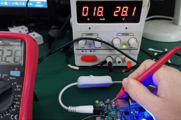
II. Power-on detection
After the above inspections are passed, power-on testing can be performed. At this time, it is necessary to have some experience in electronic basics and maintenance skills. Generally speaking, it is necessary to focus on checking the input end of the power supply, the switching triode, the power protection circuit, and the output voltage and current of the power supply.
If the power supply starts and stops immediately, the power supply is in the protection state, and the voltage at the protection input pin of the PWM chip can be directly measured. If the voltage exceeds the specified value, it indicates that the power supply is in the protection state, and the cause of the protection should be checked in detail. Since high voltage is involved, friends without electronic basics are recommended to be careful when operating.
III. Common faults
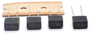
1.Fuse blown
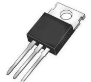
In general, a blown fuse indicates that there is a problem with the internal circuit of the power adapter. Since the dry power supply works under high voltage and large current, fluctuations and surges in the power grid voltage will cause the current in the power supply to increase instantaneously, resulting in the blowing of the fuse. The key is to check whether the rectifier diode at the input end of the power supply, the high-voltage filter electrolytic capacitor, and the inverter power switching tube are damaged or not. If the fuse is blown, it should be checked whether the electronic components on the circuit board have been burnt or the electrolyte has overflowed. If the above situations are not found, use a multimeter to measure whether the switching tube is broken.
2.No DC voltage output or unstable voltage output
If the fuse is intact and there is no output voltage under load, the main reasons may be: 1) an open circuit, short circuit, overvoltage, or overcurrent protection circuit failure in the power adapter; 2) the oscillation circuit does not work properly, and the power supply is overloaded; and 3) the rectifier diode in the high-frequency rectification and filtering circuit is breakdown or the filter capacitor is leaking. After measuring the secondary components with a multimeter and ruling out the possibility of high frequency rectifier diode breakdown or load short circuit, if the output is still zero at this time, it can be determined that the control circuit of the power supply is faulty.
3.Poor load capacity of the power adapter
Poor load capacity of the power adapter is a common fault. Generally, it occurs in power supplies that have been operating for a long time, mainly due to the performance degradation of various electronic components, unstable operation of the switch tube, and failure to perform timely heat dissipation. The stable voltage regulator diode should be checked for heating, leakage, rectifier diode damage, high-voltage filter capacitor damage, etc.
Conclusion:
Power adapter maintenance is not difficult. Generally, power supply faults can be summarized as: fuse blowing, rectifier diode damage, filter capacitor open or breakdown, switch tube breakdown, and power supply self-protection. JPTPOWER has more than 10 years of R&D and manufacturing experience. If you have any questions about power adapters, please contact us.