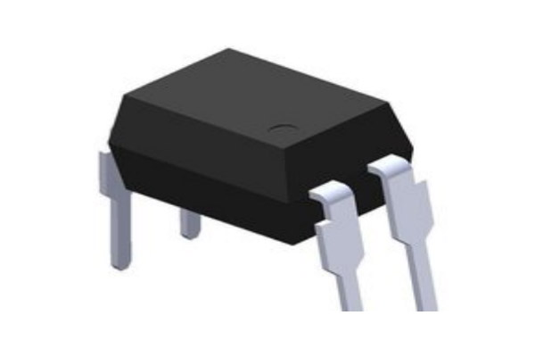
The application of optical coupler in switching power supply is very common. In the design process of different switching power supply, the role of optical coupler is also different. Here we will be through two switching power supply in the application of optocoupler connection case, for the new engineers just started to contact the design of electronic products, introduce the role of optical coupler in switching power supply, and its working principle knowledge.
The first common connection in which optical couplers act as optical coupling feedback in switching power supplies is shown in Figure 1 below. In Figure 1, we can see that Vo is the output voltage and Vd is the supply voltage of the chip. The com signal is connected to the error amplifier output pin of the chip, or the internal voltage error amplifier of the PWM chip is connected to the in-phase amplifier form, and the com signal is connected to its corresponding in-phase pin. Note that the ground on the left is the output voltage ground, and the ground on the right is the chip supply voltage ground, and they are separated by optical coupling.
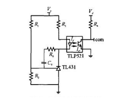
Figure 1.Common connections of optical coupler for optocoupler feedback
When using the switching power supply optocoupler feedback method provided in Figure 1, the working principle of the optical coupler in the whole system is as follows: when the output voltage rises, pin 1 of TL431 is equivalent to the reverse input end of the voltage error amplifier in this process, and then the voltage rises, pin 3 is equivalent to the output pin of the voltage error amplifier, and its own voltage will drop at this time .
Therefore, the primary side current 1f of the photocouple TLP521 increases, the output current Ic of the other end of the photocouple increases, the voltage drop on the resistor R4 increases, the com pin voltage drops, the duty ratio decreases, and the output voltage decreases. Conversely, when the output voltage is reduced, the adjustment process is similar.
The second common connection of optical coupler in switching power supply is shown in Figure 2 below. The difference between this connection method and the first connection method is that there is an extra resistor R6 in Figure 2. The purpose of this resistor is to inject an extra current into TL431 to avoid TL431 from not working properly due to too small injection current. In fact, if the resistance R3 is selected appropriately, the resistance R6 can be omitted. The adjustment process is basically the same as that in Figure 1.
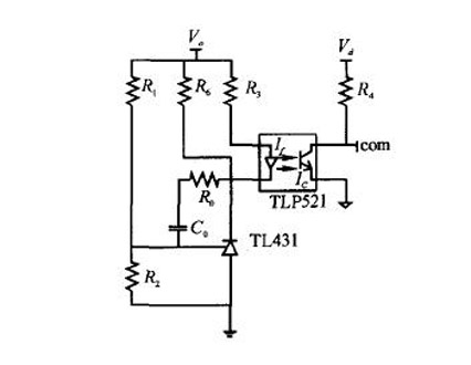
Figure 2. Common connection of optical coupler in switching power supply
We can see that the optical coupler in the two typical switching power applications provided above, its main role is isolation, feedback signal and switching. In the switching power supply circuit, the power supply of the optical coupler is provided from the secondary voltage of the high-frequency transformer. When the output voltage is lower than the voltage regulator, the optical coupler is switched on and the duty ratio is increased, making the output voltage rise.
Otherwise, the photocoupling is turned off to reduce the duty ratio and the output voltage is reduced. Denier high frequency transformer secondary load overload or switching circuit fault, there is no optocoupler power supply, optocoupler controls the switching circuit can not vibrate, so as to protect the switch tube from being broken down.
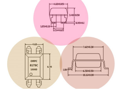
Optocoupler Size
Regarding the key components of the power adapter, you can consult the electronic engineer at JPTPOWER, please contact us.
